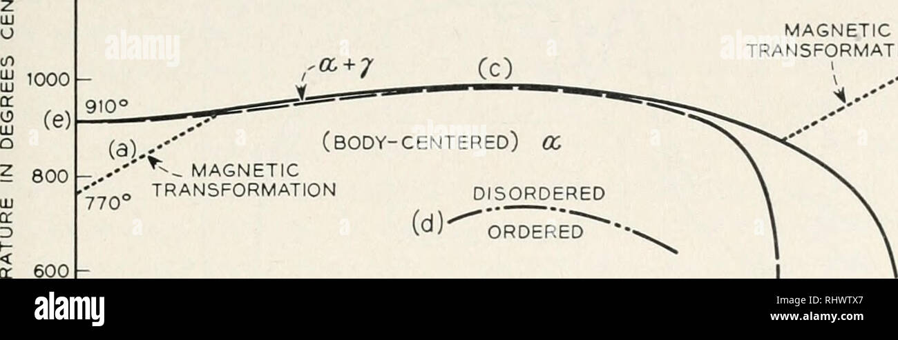
Cobalt Carbon Phase Diagram
Access options buy single article.

Cobalt carbon phase diagram. This is a preview of subscription content log in to check access. The transverse rupture strength of tungsten carbide wc tools bonded with cobalt is a function of the carbon content. Price includes vat for usa. The fe c phase diagram is a fairly complex one but we will only consider the steel part of the diagram up to around 7 carbon.
Isothermal section of w co c equilibrium diagram cooling curves of three phase alloys beta graphite wc and beta eta wc metastable equilibrium diagram wolfram cobalt carbon. The graph is quite complex but since we are limiting our exploration to fe3c we will only be focusing up to 667 weight percent of carbon. Wolfram carbon equilibrium diagram x ray spectrometer pattern of eta and theta phnses x ray spectrometer pattern of kappa phase 14000c. The milled powders are pressed into shape.
Instant access to the full article pdf. Polycrystalline samples of lixcoo2 and coo2 x 00 were. A lubricant is added to the blended powder mainly to reduce the friction. The most preferred microstructure formed on cooling from the sintering temperature consists of just two phases.
Cobalt outdiffusion and carbon phase composition at the wc10codiamond film interface investigated by xps sem raman and sims. 972 4 8293754. Phase diagrams tungsten cobalt carbon w co c phase diagram. Russell berrie nanotechnology institute technion haifa 32000 israel.
The cobalt may also undergo a phase transformation during milling from a predominantly cubic structure to a hexagonal close packed structure. 3 wc co hardmetals 4 between the powder mixture and the surfaces of the tools and also to minimize the tendency to form cracks 15. Mse 300 materials laboratory procedures university of tennessee dept. 972 4 8293727 fax.
Of materials science and engineering 3 phases in fefe3c phase diagram a ferrite solid solution of c in bcc fe stable form of iron at room temperature. Representation by basal projection. Also both alloys contain a small amount of trace elements. Rent this article via.
Phase diagram of lixcoo2 with that of naxcoo2 to highlight similarities and differences between the two systems. Both steel and cast iron are a mix of iron and carbon. Wc particles uniformly embedded in the matrix of face centered cubic fcc cobalt. The different features in the two systems are discussed from the crystallographic point of view.
Due to their excellent magnetic wear corrosion and high temperature properties the cobalt chromium co cr alloys have been of great industrial and biomedical interest eg magnets sputtering thin film high coercivity high density magnetic recording media in hard disks surgical and dental implants turbine disks in early jet engines. Indicates presence of a phase diagram. The maximum. Nishizawa calculation of phase diagrams of the iron copper and cobalt copper systemscalphad 4 83 1980.
K ishida 1 t nishizawa 1 journal of phase equilibria volume 12 pages 417 424 1991cite this article. The iron carbon phase diagram is widely used to understand the different phases of steel and cast iron. Electronic phase diagram of the layered cobalt oxide system.


